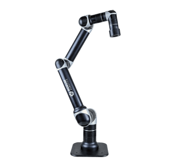
A brushless motor with a controller constitute an electronically commutated propulsion mechanism. In the mechanism, electronic commutation does the job of switching the current to maintain rotation and torque generation—the same as brushes in a mechanically switched mechanism. Let us explore the mechanics and the underlying control logic.
The concept
In an electronically commutated solution, the drive unit is typically a brushless alternating- (AC) or direct current (DC) motor. In contrast to brushed counterparts, the actuators incorporate transistors to perform the function of mechanical commutators. Another brushless design peculiarity: winding coils are removed from the amature to the stator, while magnets become part of the rotor assembly.
A brushless motor controller is the command hub employing electronics to regulate voltage and amperage fed to the drive unit coils. In this way, it instructs the engine to start or halt, turn forward or backward, curbing velocity, adjusting moment of force and other parameters. All commutation inputs are programmable.
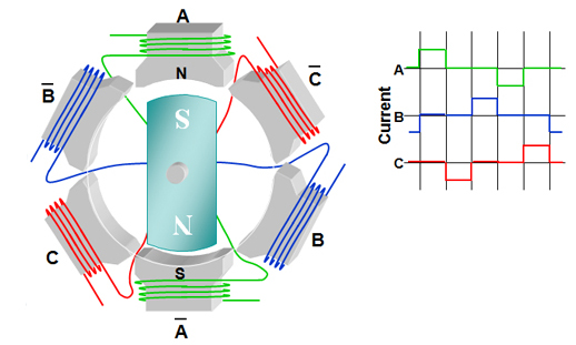
A brushless motor and a controller are matched based on the desired type of movement—continuous rotation at constant speed, incremental propulsion, etc. The devices can be used as stand-alone components or encapsulated into the actuator shell.
Advantages of a brushless motor with a controller
With electronics-enabled governance, brushless solutions obtain a range of benefits:
High efficiency, especially in fractional horsepower applications, even at speeds lower than rated values. Though varying from vendor to vendor and depending on load and power supply, efficiency of a controller-equipped no-brush solution outpaces that of other actuators. Whereas the average value for ECM solutions is about 60%, shaded-pole mechanisms feature 30-50% and permanent split capacitor engines—40%. The superior performance is associated with lower friction resulting from removed brushes and improved regulation via electronics.
Technical details:
Fractional horsepower application—a system requiring a compact-size motion hub capable of running at a power rating of less than one horsepower.
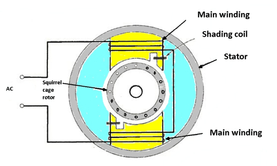
Shaded-pole engine—a single-phase actuator fed with AC power. It consists of an unshaded section and a shading coil—a copper ring with auxiliary winding. No brushes, no commutator, no capacitor or switches, which contributes to simplicity and reliability of the mechanism. The shading coil induces magnetic flux to move from the shaded to the unshaded section, thus creating a spinning magnetic field affecting the rotor. The field is not strong, though, which is why the type has low starting torque ratings.
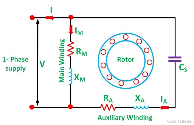
Permanent split capacitor motor—is a split-phase drive with major elements comprising a cage rotor, main and auxiliary windings, and a capacitor. Both the capacitor and the auxiliary winding are permanently engaged. This ensures outstanding power factor, while eliminating the need to embed a start switch, and enables the engine to provide performance similar to a stable two-phase system. Similarly to shaded-pole solution, permanent split capacitor engines generate less rotational force at the start than at full load.
- Improved motion regulation, reliability, and safety. No sparks and reduced wear due to eliminated mechanical switches, which translates into lower failure rates and ignition risks. A microprocessor controller provides precise adjustment of the magnetic field, while minimizing eddy currents and associated losses. Adding a feedback sensor to form a closed-loop control circuit improves responsiveness of the system to commands.
- Cover a wide range of operational conditions and parameters. One brushless model with a controller is claimed to substitute a number of conventional (e.g., induction) models. As a result, the customer gets a chance to cut and simplify inventory, thus reducing operating costs. Because motion parameters are controlled from software, the customer can configure it to match exactly the operating conditions.
Technical details:
Induction motor is a type of AC actuators where current on the rotor—and, consequently, torque— is produced by electromagnetic induction in the stator. Therefore, no electrical connection is required between the stator and the rotor.
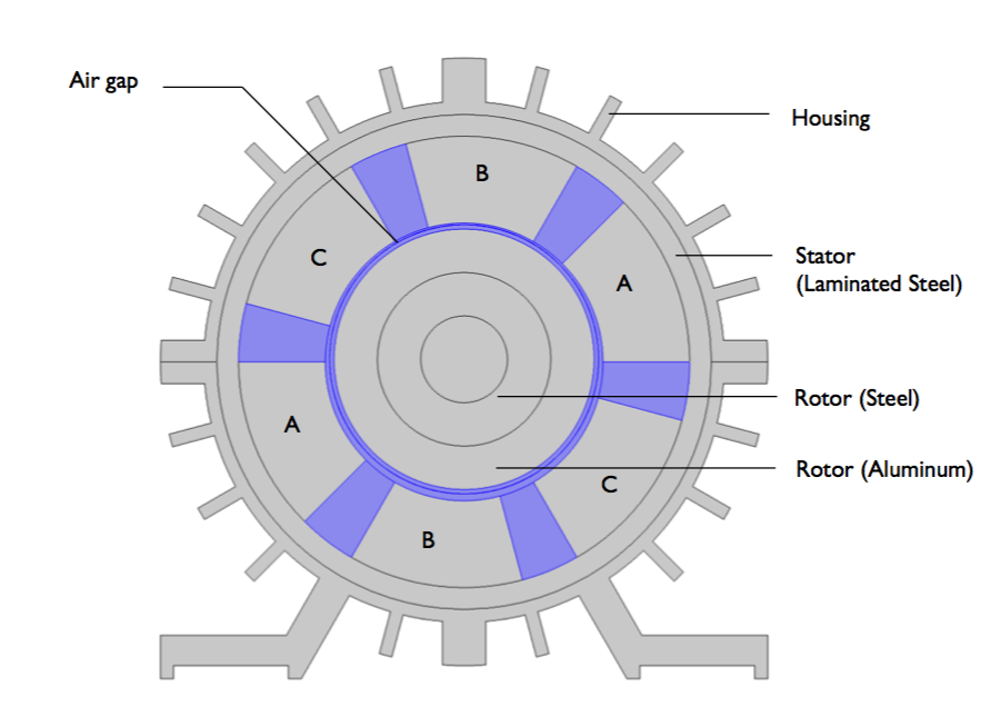
Electronically commutated actuators produce less waste heat. The improvement allows to save energy and to extend life of such highly wearable components in a motion system as windings and bearings. In addition, EMC drives boast quiet operation, optimized durability, and require minimal servicing.
Control logic
There are several methods how a brushless motor controller can govern performance.
Trapezoidal
The method implies utilizing a Hall-effect sensors to keep track of rotor angles, switching phases in proper sequence and with adequate timing. Measurements are taken at two active phases simultaneously, while the third one remains de-energized.
The sensors are mounted on the back of an engine, spaced at 120 degrees, and output logic bits. Each individual combination of the bits from the three devices describes certain direction of phase current vector. In all, there are six such combinations available, which is viewed as a limitation of the technology.
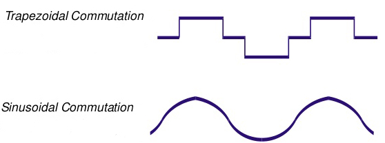
Sinusoidal
Sinusoidal commutation involves modulating sine waveforms in all three windings. As a result, torque ripple and noise level is less significant than in case with the six-step type. Simultaneously, rotation is smoother, which is associated with enhanced efficiency and high moment of force.
However, implementation of the control logic requires a feedback device with a better resolution than provided by Hall sensors—such as an encoder, which adds to the cost of ownership. Real-time processing of PWM sine values involves more complex calculations than for trapezoids. Performance at high velocities is impaired because current bandwidth are limited due to impedance.
Field-oriented (FOC)
Similarly to the previous case, field-oriented control output is also a sinusoidal waveform. However, the type of governance enables to eliminate the efficiency drop at increased speeds, typical of sinusoidal regulation.
The field-oriented method takes time dependence out of calculations, decomposing the stator current into two components—torque and flux. The components are controlled via individual proportional-integral regulators. The devices monitor errors, adjusting phase and voltage to achieve desired moment of force and flux values.
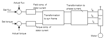
Whereas field-oriented regulation appears to be mathematically intensive, benefits outweigh. The FOC logic provides smooth rotation and superior efficiency over a wide speed range, great dynamic response, and high torque even at zero velocity.
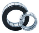
FMI brushless models are supplied as rotor-and-stator assemblies, ready for integration with a feedback device and a microcontroller, that users can put into a housing of their own design. Controllers are available as an option, featuring:
- Support of field-oriented commutation method
- Control algorithm matched uniquely to the motion core
- Encoder-ready design with absolute encoder as recommended choice for feedback
- 20A continuous amps output
The FOC approach is a proven way to boost performance of a brushless AC engine towards optimum efficiency, enabling it to deliver consistent moment of force with only slight ripple. Boasting fast response time, FOC-controlled solution is an asset to highly dynamic applications with frequent load variations.
With the field-oriented governance logic embedded in the controller firmware and an absolute encoder, you can create a closed-loop circuit to drive your FMI in a puppet-like manner with inch-perfect precision.
