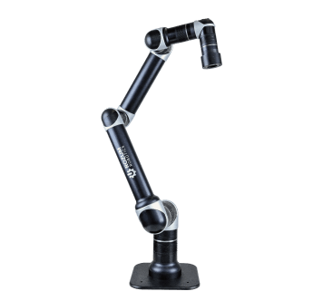
Pertaining to open-loop mechanisms, steppers function efficiently without feedback because the user can derive engine positions simply from counting incremental steps. In contrast, coupling a an encoder with a servo motor is essential to achieve inch-perfect movement precision expected from the engine type.
The role of an encoder in a servo motor
According to the classical definition, a servomechanism is an engine pieced together with a feedback sensor and a controller to form a closed-loop control circuit. In the circuit, the sensor orchestrates the following operations:
- Observes the mechanical motion of the actuator shaft—a change of position and the rate of change.
- Converts the mechanical input into an electrical impulse and transmits a series of such impulses as a quadrature signal to a controller.
To obtain velocity or angular displacement data, an encoder in a servo motor can be replaced with a potentiometer, a resolver, or a Hall effect transducer. However, the alternatives demonstrate inferior robustness, responsiveness, and reliability in most cases.
Advice on selection
Choosing a sensor to match a servomechanism requires exploring the specifics of the system where the assembly is supposed to be integrated, in particular:
- Type of propulsion. An application, where movements are along a straight-line trajectory, demands a linear detector. In machines performing angular displacements, the preferred type is rotary.
- Mounting method. The encoder body can incorporate a shaft, in which case it is assembled with the drive unit by means of a coupling. While enabling proper alignment, the coupling also isolates the sensing element from a drive unit, both mechanically and electrically.
An alternative is a hollow-shaft mounting arrangement, using a springed tether. The method eliminates the need for alignment and associated failures, but demands special measures to be taken to ensure electrical isolation from the drive unit. A third option is bearingless mount composed of a sensing element installed on the engine face and a magnetic element—on the shaft.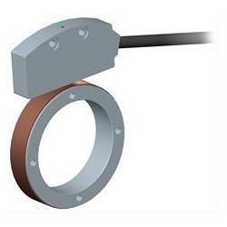
Required output
The choice is typically between incremental and absolute. Incremental mechanisms are intended mainly to track speed since they provide no exact indication of positions. Absolute transducers enable both speed and angular displacement monitoring, enabling the user to determine with certainty where the motor shifted as a result of executing a command.
Operating environment
The user should study carefully the environmental aspects: presence of chemicals, moisture, as well as particulates, and vibration. The characteristics serve as a basis to establish preferred motion detector specifications—the IP rating, explosion-proof design, etc. Say, IP50 sensors are suitable for environments with excessive dust generation, while IP52-rated ones are deemed to be waterproof.

Furthermore, the operating environment dictates a particular sensing technology. Optical transducers are resistant to electromagnetic interference, but susceptible to dust contamination. Mechanisms employing the magnetic technology are sensitive to factors, such as presence of an electromagnetic field or ferromagnetic particles.
Essential parameters
Knowing application particulars is certainly both a necessity and a preclusion of making the wrong choice. In addition to the investigation of intended use, the user should match the specifications and conditions of a measured system to essential parameters of an encoder. The parameters include:
- Resolution—the smallest distance that can be measured within one shaft turn or within a distance of 1 mm/ inch. The value is expressed either in pulses per revolution, in which case we speak about incremental sensors, or in bits, if we refer to absolute devices. Integrating a high-resolution encoder will not necessarily upgrade the overall system precision. In some cases, controllers are not able to handle the response frequency of the feedback device. A general recommendation is that resolution should be twice or four times as high as that of the associated machinery.
- Accuracy—the extent to which the actual measurement deviates from the recorded result. Specified in arcminutes, arcseconds, or microns (linear), the magnitude depends on a bunch of factors, attributable to the detector mechanics or the controlled machinery properties. As an example, backlash in geared servomechanisms can be a source of additional error. A related parameter of significance, especially in systems demanding ultra-precise positioning, is integrated non-linearity (INL). It represents maximum peak-to-peak deviation between the actual and the ideal measurement output.
- Repeatability—the ability to reproduce the same reading with identical precision. In general, the measurement is expected to exceed claimed accuracy by 2 to 10 times. Mind that repeatability of the encoder is only part of the overall system repeatability. Mechanical errors resulting from gear backlash, hysteresis, etc. significantly reduce the parameter value.
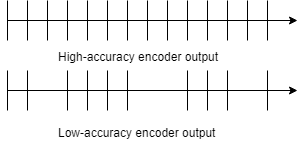
Finding a perfect match is rather about choosing an optimal combination of accuracy, resolution, and repeatability than getting maximum magnitudes. To illustrate, the best option to use in a robot would be a feedback component featuring average accuracy, but ultra-high repeatability.
Motion response in RDrive engines
Initially intended to be used in robotic solutions demanding ultra-precise movement control, RDrive actuators incorporate two encoders with the following features:
- Absolute measurements, taken at rotor and output shafts, give inch-perfect results to provide the user with a comprehensive motion profile of an application.
- No homing procedure required since readings are non-volatile.
- Magnetic sensing technology proofs the devices against numerous hazards typical of heavy-duty industrial environments, such as dust, moisture, etc.
- 19-bit resolution allows to determine the drive position with exactitude of a thousandth degree.
The mechanisms are already matched with the drive unit and the controller, which saves the trouble of going through the selection process and designing the integration. All it takes to start getting feedback and driving your machinery with precision is to spend one and a half minutes to connect and launch your RDrive servo.
