A shaft encoder vs. an absolute shaft encoder—the seeming distinction is a single word. In reality, the underlying metering technology makes a major difference. Replacing the “absolute” part with “incremental” would change the meaning altogether. Read on to get a better idea of related implications.
Rotary or shaft encoder
The term refers to a class of metering mechanisms that monitor angular displacements of a spinning object. For estimating travel along a rectilinear path, it is common practice to utilize the linear variety.
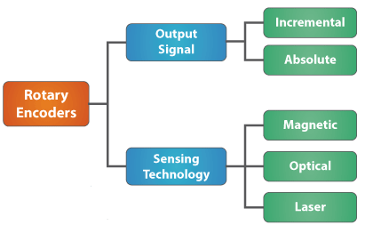
A rotary encoder can have a hub or a hollow shaft coupled to or clamped onto that of an attached spinning object. Its internal mechanical arrangement depends on the employed sensing technology (e.g., magnetic or optical) and the expected output (e.g., incremental).
Linear transducers comprise a scale translating displacements into specific codes and a sensing element reading the encoded data to convert it into electrical signals. The scale can be either transmissive or reflective and use Ronchi ruling or phase grating. Possible configuration options: self-supporting, track-mounted, or thermally mastered.
Technical details
Named after the Italian scientist Vasco Ronchi, the Ronchi ruling is a mask to enable optics-based measurements formed by a pattern of evenly spaced opaque and transparent stripes.

Phase, or diffraction, grating is a mask that splits light into multiple beams spreading in various directions. Beam orientation depend on the spacing of the mask grating and the wavelength of the received light.
Linear models are available in two modifications—enclosed or open. Enclosed models have a metal housing protecting the scale from negative impacts, such as dirt and debris contamination. However, increased friction and hysteresis typical of the design degrades accuracy. To achieve a higher precision, the open-type modification is preferable.
Whether of the linear or rotary variety, a transducer transmits measurement results to a master system (e.g., a motor controller). In the course of processing, the master decodes displacement signals, while deriving speed and other important motion-related parameters.
What is special about absolute shaft encoder
A rotary encoder of the subtype is supposed to implement a specific sensing principle, to return certain response, and to be used in particular applications.
The general definition expands into a more detailed description, where the mechanism is claimed to possess the following features:
- Measured values determine how far a rotating object has moved from a zero coordinate. The coordinate remains unchanged irrespective of system states (e.g., whether the hardware is on or off).
- Each reading correlates with a unique binary code, with users obtaining inch-perfect feedback on the object’s displacement angles at any given moment.
- Because such sensors return non-relative values, no homing procedure is needed at power-up to identify a measurement reference. The devices require no backup battery, no external buffer to help restore data after a power outage. All data arrays are available immediately upon switching, even if power supply is interrupted during operation.
- The detector reads parameters within a single revolution, in which case it is referred to as single-turn, or over multiple 360-degree revolutions—and then gets a multi-turn prefix to its name.
- The encoder modification is immune to noise interference and returns inch-perfect motion feedback. Therefore, the device brings added value in applications targeting at high-precision speed and trajectory control and imposing enhanced safety and data integrity standards. Single-turn modifications are an outstanding choice when sensing functions are performed at slow rates or have long-lasting idle periods.
- Supporting a variety of data exchange protocols, the sensor subtype enables easy integration with electronics on the customer side.
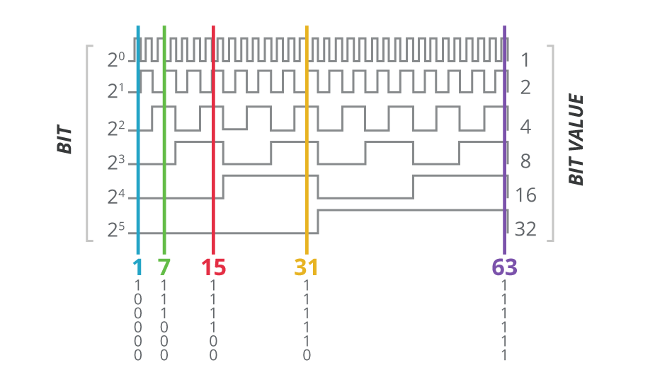
A shaft encoder of the subtype propels precision of angular positioning to a new level. The hardware type an asset to handle tasks, such as servo motor orchestration and robot motion control.
Alternative position-sensing
Reliable, accurate, and robust, the absolute shaft encoder is nevertheless not a fit-it-all solution. Numerous manufacturers offer alternative feedback mechanisms that may be a better choice under certain circumstances.
An incremental shaft encoder produces an impulse every time a shaft moves warning about change of location, but returns no exact coordinates of the object position after the change. Such meters require implementing a homing algorithm to restore a zero reference, or using a battery or a buffer to avoid referencing issues after planned or unplanned shutdowns. Cheap and simple, the detectors are preferable in systems that focus rather on pulse counting and frequency control.
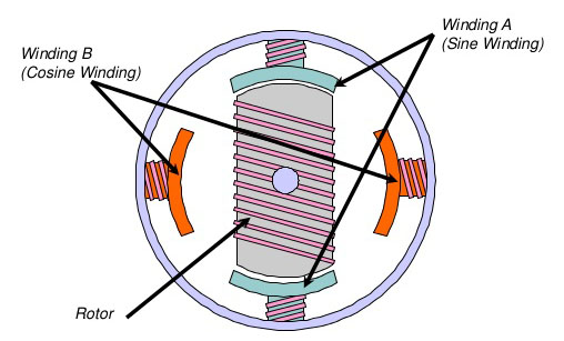
Dating back to the World War II, resolvers employ a well-established measuring technology. Each sensor of the type incorporates a laminated cylindrical stator-rotor assembly and two mutually perpendicular auxiliary windings. One of the windings is stationary, while the other rotates synchronically with an attached object. The resolver derives its response values from the way the two magnet fields change their strength and spatial location during the interaction.
Thanks to the simple design, resolvers demonstrate stable performance under tough conditions, such as extremely low or high temperatures, excessive shock and vibration. However, their accuracy is inferior to the above described transducers. To obtain digital return from resolvers, users will most probably need to install additional electronics.
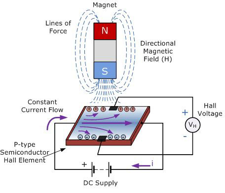
Hall-effect metering devices generate specific voltage magnitudes when exposed to magnet force. Inside the device housing, there is a narrow semiconductor strip passing a constant current flow. The magnetic flux affects the strip, causing charge carrying electrons to shift closer to the edge, which produces voltage differential across the strip. By orientation, the magnetic flux should be oriented vertically relative to the input current flow. Hall-effect elements not only react to variations in magnetic flux density, but also sense proximity of a static magnet field.
An example of a position-sensing application—a Hall-effect transducer linked to a brushless DC motor to monitor rotor movements. Major values of the technology are seen in the following: simplicity, robustness, immunity to vibration and contamination, and reliable operation in heavy-duty environments. The non-contact design allows to reduce wear and maintenance scope.
On the downside, Hall-effect transducers have a significant drift, which requires additional compensation arrangements. To interface with microprocessor systems or controllers, the detectors should be integrated with digital electronics.
Absolute encoding in RDrive servos
From the available options, specialists at Rozum Robotics have decided on equipping RDrive servo motors with absolute shaft encoders—a reasonable resolution in lieu of the following:
- RDrive servo motors are intended to enable precise angular positioning. A rotary encoder is just the right device to provide accurate feedback on rotational displacements.
- Supporting the BiSS protocol, the feedback mechanisms can freely communicate with controlling electronics (e.g., controllers).
- Absolute output enables motion control with the highest possible precision. From the response, controllers derive exact motor whereabouts, compare the values with the commands, and make necessary corrections to trajectories.
- Measured motion parameters are accessible to users at any moment, without any external aids, additional costs or efforts.
- Measurements are made with 19-bit resolution at two spots simultaneously—on the output shaft and on the rotor.
The two encoders do their job of closing the motion control loop perfectly. Leveraging the technology, Rozum Robotics implements in its RDrive actuators such quality as high accuracy and repeatability—typical of and desirable in servomechanisms.

