When first diving into the gears’ world, you may come across several terms: gear ratio and contact ratio. You do not have to know how to calculate gear ratio to choose the right one, as you can find it in the product description, but understanding how it works will make your choice more… calculated. Use this article as your personal flashlight and you won’t get lost.
To make it simple not only in word but also visually, we tried to explain the whole stuff using Lego. So, let’s start, or as scuba divers say, let’s get wet!
The Big Gears Family
First there was the Wheel. Then came a Gear. Gears come into play for one of the following reasons:
- to reverse the direction of rotation
- to keep the rotation synchronized
- to increase or decrease the speed of rotation
- to move rotational motion to a different axis
Humanity has known the gear systems (known as ‘trains’) since at least four ages BC in China, so the first invention may even be much older. During these 2,000 years, they developed and divided into numerous dynasties. Let’s mention some of the most powerful representatives. Three big train groups exist based on the orientation of the gear axes:
I. Parallel Axes Trains: Where the teeth are parallel to the axis
1. Spur

When someone hears the word ‘gear’, in most cases, a simple spur gear comes to their mind.
Spur type is applied in a wide range of industries and it is the easiest to find on the market in all the sizes.
2. Helical

A cylindrical gear with helicoid teeth (they are at an angle to the axis of rotation of the gear) can handle more load force than spur one, but they are less efficient. During the motion, there are sliding contacts between two helical gears, which produce axial thrust of gear shafts and increased heat.
3. Rack and Pinion
.jpg)
This is a linear gear (the rack) comprised with a spur gear (the pinion). Rotary driving of the pinion causes the linear motion of the rack. Driving the rack causes the pinion to rotate. This system is the simplest tool to convert rotary motion into linear motion and back. You can read more on linear drives and its advantages here.
4. Internal Gears

This is another one with cylindrical shape, but the teeth here are inside the ring. As a rule of thumb, these gears are found in planetary mechanisms. Thanks to this design, the vibrations and losses in planetary drives are minor. The rotational stability improves the reliability and repeatability of the movement. Planetary drives offer greater efficiency and accuracy than other systems.
II. Intersecting Axes Trains: Where the gear axis cross at a point
1. Bevel
.jpg)
In a bevel gear, the shaft axes intersect. Usually, the angle between the shafts is 90 degrees, but the train exists with other angles as well (except for 0 and 180 degrees). This angle flexibility lets us widely use the bevel system to change the force direction. For example, from horizontal to vertical. According to the shape and the number of teeth, there are miter, spiral, and straight bevel gears.
III. Nonparallel Axes Systems:
1. Worm and Worm Wheels
.jpg)
Worm train consists of a normal spur gear (worm wheel) and a gear with one tooth (the worm), but this one tooth is like a screw thread. The motion of the wheel and the gear is a mixture of sliding and rolling actions. Sliding moves cause friction and heat that decrease the efficiency of the train up to 50%. At the same time, this type of meshing ensures very quiet performance, which makes worm suitable for usage in environments where noise should be minimized. Even if the efficiency is relatively low, worm trains provide very high reduction ratios.
2. Screw
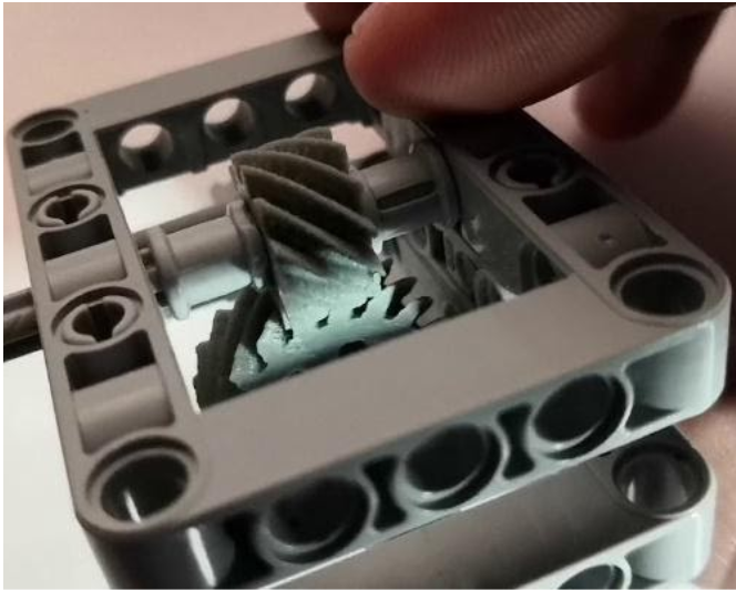
The screw train is a pair of crossed helical gears that transmit motion and power between perpendicular but not-intersecting shafts. They do not have a standard rolling movement during their interaction but a screw motion (that’s why screw).
Gear Ratio
Every mentioned train type has its strengths or weaknesses, but the main parameter of meshing gears still is the gear ratio. Since each part in the train has a different number of teeth, each of the gears rotates at a different speed. Gear ratio shows this difference.
Knowing a ratio in a robotic project is crucial for:
- Finding the rotational speed of drive gear.
- Reaching speed and torque balance. If the gear ratio is 1:1, the amount of torque is the same, and the speed is the same. With the ratio 1:4, for example, you’ll get less torque but more speed. With the ratio 4:1, you would cut the speed but boost the torque.
- Optimal servo motor sizing. If the motor inertia is too high relative to the load inertia, the motor is bigger, meaning that it was more expensive than it’s necessary to produce it, and the motor uses more energy than needed for the application.
- Minimizing errors and increasing accuracy. An ideal gear ratio is the lowest inertia that can produce maximum acceleration without making the system unstable, overheated, or inaccurate.
How to Calculate Gear Ratio?
Let’s start with the simplest gear train with only two meshing gears. The first gear attached to the motor shaft is called a "drive". The second attached to the load shaft gear is the "driven" one.

To calculate the gear ratio:
- Count the number of teeth on each part. In our example, the smaller drive has 21 teeth and the driven has 28 teeth. Besides, when we speak about spur type, the one with more teeth is called the “gear” and the one with the fewer teeth is the “pinion”.
- Divide the number of driven gear teeth by the number of drive gear teeth. In our example, it’s 28/21 or 4 : 3. This gear ratio shows that the smaller driver gear must turn 1,3 times to get the larger driven gear to make one complete turn.
Now, stay calm and brace yourself: A high numerical gear ratio is called a “low gear”. A low numerical gear ratio is a “high gear”. Low gears cause fast acceleration and are suitable for smaller engines. High cause better cruising and higher top speed so they are applicable for more powerful engines.
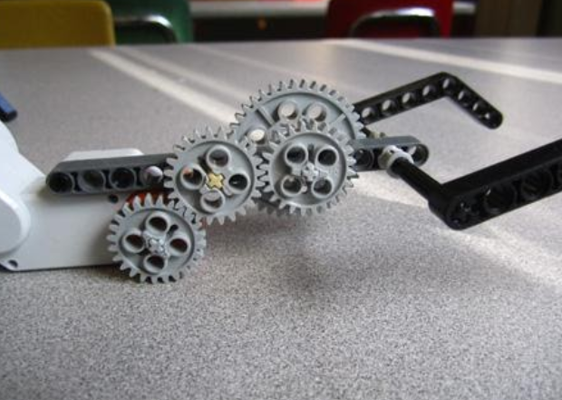
But what if the system incorporates more than two elements? The intermediate gears or so-called "idlers’’ are used to keep or to change the direction of rotation.
You can apply the ratio formula to each pair of wheels, but you don't actually need to do that. No matter how many idlers there are in the train, the final gear ratio is the ratio between the driver and the driven wheel. For easy calculation, you can use this Lego Online ratio calculator.
Contact Ratio
Another important parameter when choosing gears is the contact ratio. It represents the number of teeth meshing at the same time. If multiple teeth are in contact, the load is shared and the operational life of the mechanism is improved.
Knowing a contact ratio in a robotic project is crucial for:
- Torque: more teeth in contact = the mechanism transmits and withstands more torque.
- Stiffness: higher contact ratio = fewer stiffness variations. This means less deflection of the teeth and transmission errors.
- Accuracy: higher contact ratio = good accuracy, fewer mistakes, and a uniform manner of system performance.
- Noise level: higher contact ratio = increased stiffness = reduced noise.
How to Calculate Contact Ratio?
Formulas for calculating the contact ratio will depend on the gear type. But when considering all types in general, contact ratio consists of two components:
Radial contact ratio, εα + Overlap contact ratio, εβ (applied only for helical or spiral types).
More on calculating gear contact ratio you can read here and here.
So, hopefully, you now know a bit more about gears, it’s differences and parameters, and can easily dive deeper into the Big Ocean called “Motion Control’’.




.jpg)
.jpg)
.jpg)


